Design and Development of an in-cylinder pressure-measurement system
We explain the final-year project of Michael Garces de Gois – the winner of the CAR/Isuzu Engineering Challenge
AN inquisitive mind is a key characteristic of a good engineer. Being able to apply engineering knowledge and skills to answer technical questions firmly puts an engineer in the “excellent” category. Michael’s desire to understand basic diesel combustion gave rise to his final-year project in which he had to measure pressure waves in one of the most hostile environments, the combustion chamber of a small, single-cylinder diesel engine. We take the journey with him as he unlocks the mysteries behind diesel combustion.
The objectives of the project
Setting clear objectives at the start of a project is key because the results are evaluated against these goals. These were Michael’s objectives.
- Select and procure all devices necessary for data-acquisitioning of the in-cylinder pressure and crank angle of a Yanmar LN100 engine.
- Design all fittings necessary for proper installation of the devices to ensure accurate measurements and good repeatability.
- Develop a software programme (LABVIEW) to perform the data acquisition of the measured pressure and crank angle while the engine is running on the test bench.
- Develop a mathematical programme (MATLAB) to calculate the heat release of the diesel fuel using the data obtained by LABVIEW.
- Analyse the heat-release rate of the diesel fuel.
The hardware
The test engine:
For the purpose of this project, a Yanmar LN100 industrial, single-cylinder diesel engine was chosen because it is relatively inexpensive and simple enough to modify.
Power: 7,46 kW @ 3 600 r/min
Torque: 27,5 N.m @ 2 300 r/min
Fuel supply: Direct injection
Weight: 48,5 kg
Pressure transducer:
An Optrand M3x0,5 miniature pressure sensor with a pressure range up to 250 bar was chosen to measure the pressure inside the combustion chamber of the engine. This was done after a number of pressure transducers were evaluated on several criteria, including the fact that it had to be small enough to allow it access to the combustion chamber. A high-frequency transducer was required to capture the rapid changes in combustion pressure at all engine speeds. Lastly, the transducer needed to be robust to withstand the harsh environment of an internal-combustion chamber.
Rotary encoder:
A Leine & Linde RHI 503 hollow-shaft incremental encoder was chosen to track the crankshaft angle and determine the exact position of the piston inside the cylinder while the engine is running. This enables the phase of the four-stroke cycle to be determined, as well as the theoretical volume of air above the piston in the combustion chamber at all crank angles.
Machining and manufacturing
In order to fit the pressure transducer and rotary encoder to the Yanmar LN100 engine, it was necessary to design and manufacture a few special components and machine the cylinder head of the engine to realise a functional test unit. In short, the following took place:
Encoder mounting plate:
The body of the shaft encoder had to be mounted inline with the crankshaft axis and led to the design and manufacture of a mounting plate to provide a stable platform. Careful consideration was given to the shape of the plate so that it would not hinder airflow to the air-cooled engine.
Rotary encoder shaft:
A shaft and mounting had to be designed and manufactured to enable the extension of the crankshaft for the purpose of fitting the rotary encoder to pick up the crank’s rotational position.
Cylinder-head machining:
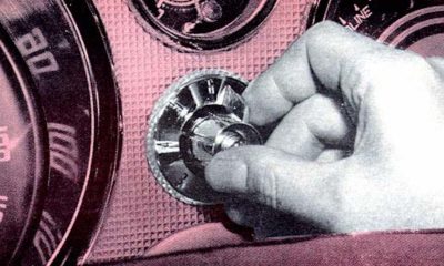
The most important machining aspect of this project was to machine a tapped hole into the cylinder head to allow the fitment of the pressure transducer. A technical drawing for the procedure was prepared after careful consideration of the position of the pressure transducer in the combustion chamber. A decision was made to locate the pressure sensor on the outer edge of the piston bowl so as not to interfere with the injector and valve (see picture) operation. This allowed direct pressure measurement of the in-cylinder gases.
The test setup
After assembly of the rotary encoder and pressure transducer, the engine was ready to be installed on a test bench at Stellenbosch University’s engine-test facility (pictured above) under the supervision of study leader, Richard Hains. A hydraulic dynamometer was used to measure the torque output of the engine by resisting the rotational force at any given engine speed.
Data acquisition was performed using a National Instrument (NI) 6351 analogue and digital-input module in conjunction with NI software called LABVIEW. The NI 6351 module provided connections for eight analogue input channels with a maximum capturing rate of 500 000 samples per second, fast enough to capture the pressure variations and crankshaft angle over the entire engine-speed range.
The theory
The diesel-combustion process consists of the following four stages after injection:
Ignition-delay period:
This period is the time between the start of injection (SOI) and the start of detectable combustion (SOC). At the SOI, highly pressurised fuel is injected into the combustion bowl or chamber. Upon injection, the fuel undergoes physical and chemical processes that result in an ignition delay.
Premixed burning period:
Some of the fuel that enters during the ignition-delay period will undergo the physical process of mixing with air, and the chemical dissociation process. Rapid combustion of this premixed fuel and air occurs during this period. The characteristic clatter of a diesel engine is mainly attributed to this premixed burning period.
Diffusion burning period:
Once the fuel that is injected in the ignition delay period has been consumed, the rate of heat release is controlled by the rate at which newly injected fuel mixes (diffusion) and becomes available for combustion. The flame front spreads out, enclosing the entire combustion chamber.
After burning period:
At the end of fuel injection, the remaining fuel, soot and wall-attached fuel also try to combust with the remaining oxygen while the piston is still moving downwards. NOx generation (at high temperatures) stops forming and soot burn-up slows down. Unburned hydrocarbon and carbon monoxide also remain until the exhaust valve opens and are expelled as exhaust emissions.
The results
To evaluate the success of the in-cylinder pressure-measurement system, the measured results were compared with combustion theory, including establishing that the pressure versus crank angle and heat-release results were correct.
Because the dynamometer used for the project was a hydraulic unit without motoring capability, motoring curves (pressure versus crank angle without injection and therefore combustion of fuel) were obtained by running the engine and capturing data while suddenly cutting off the fuel (see graph below on the left). The values on the graph below to the right were obtained by running the engine at 3 656 r/min and 20 N.m to show the pressure rise during the combustion of fuel. Note that peak in-cylinder pressure was 58 bar compared with 50 bar, with no combustion present.
The heat-release diagram of the Yanmar LN100 diesel engine running on 500 ppm diesel fuel (3 656 r/min and 20 N.m) is shown below. This was calculated by measuring the rate of pressure change in the combustion chamber and calculating the volume of the combustion chamber as well as absolute combustion temperature. The ignition-delay period is observed by the dip in the graph before it crosses the zero line separating negative and positive heat release. The period following this is the premixed burning period and is characterised by the rapid rise in heat-release rate and maximum heat-release peak. The diffusion-burning period is assumed as the area enclosed by the heat-release diagram and the zero line. The rest of the oscillations observed on the heat release diagram are due to the after-burn period.
Conclusion
The results correlate well with internal-combustion-engine theory, which imply that Michael did an excellent job in achieving the objectives of the project. We wish him all the best in his future career at General Motors and encourage students to consider the fascinating field of engineering.